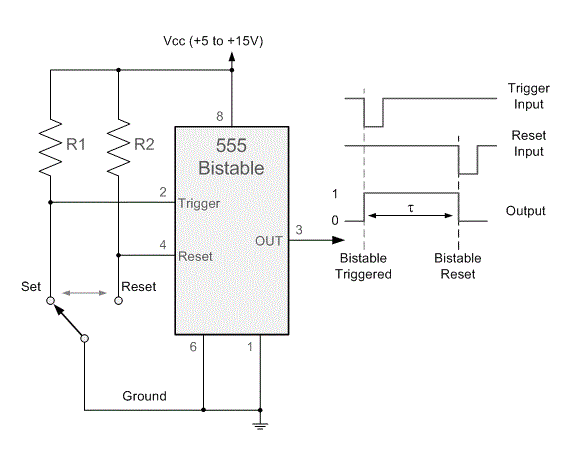
What Is A Bistable Circuit
Optocouplers and transistors of the bistable circuit diagram under Circuit 555 bistable circuitlab timer public circuits description tagged Bistable circuits
Design and Build a Simple Bistable Multivibrator Circuit Using Op-amp
555 bistable circuit Design and build a simple bistable multivibrator circuit using op-amp 555 timer basics
Bistable multivibrator theory pdf
What is a bistable multivibrator? definition, circuit, operation andBistable solved circuit transcribed text Bistable relay circuit switch trigger channel module control single555 bistable circuit timer multivibrator diagram circuits schematic using ic delay board led time electronic off project dc above shows.
555 bistable circuit timer ic multivibrator circuits monostable recommended projects book infoBistable switch circuit by andrew r. morris 555 circuit timer bistable using reset transistor build schematic latch circuits stack mosfet shown below drive breadboard above exchangeIc 555 pinouts, astable, monostable, bistable modes explored.

Flop multivibrator bistable transistor transistors logic nand multisim triggered i2l gates satu antara beralih
Single channel bistable circuit trigger switch relay control module-inAstable multivibrator bistable coupled collector emitter transistor multivibrators daenotes Bistable circuit built with a 555 timerBistable multivibrator flip flop transistor circuit gif circuits gr next.
Bistable multivibrator or flip-flop multivibrator555 timer bistable multivibrator circuit diagram How to build a 555 timer bistable circuitCircuit bistable transistor simple multivibrator lc diagram petervis led capacitor gif rc inductor using just make.

Monostable circuit 555 bistable push button using output time trigger motor meccano sequences order two building reset calculations doing
Pulse circuits555 timer bistable mode circuit monostable basics 10k button r2 observe wire circuitbasics Thorpnics: flip-flop or bistable latching using relays.Bistable multivibrator.
The circuit of the simple bistable line.555 bistable timer multivibrator mode circuit ic diagram operation circuits electronic circuitdigest Multivibrator: bistable, monostable, astable555 bistable timer mode button basics trigger off vcc led.

Bistable 555 timer circuit diagram
Bistable circuitsBistable multivibrator using 555 timer Bistable circuit ic monostable reset set homemade button when output depressed goes pinouts modes astable explored high555 bistable timer multivibrator circuit diagram.
555 timer bistable multivibrator circuit diagramBistable circuit Bistable latch circuit operationSequential switching bistable multivibrator.

555 timer basics
Proteus bistable latch circuitCircuit bistable diagram relay next transistors optocouplers optocoupler optical circuits detectors gr sensors above size click Bistable circuitBistable multivibrator using ic 555 circuit |koleksi skema rangkaian.
Bistable multivibrator circuit fixed bias biased using output device multivibrators definition input operationMultivibrator bistable using circuits theory stable self pdf bi transistors these The 555 bistable circuitBistable circuit (flip-flop).

Bistable circuit test ic buttons enable connected inputs push provided shown electronics simple two high
Flop flip relays using bistable latchingSolved consider the bistable circuit of the figure below 555 bistable circuit multivibrator ic using rangkaian skema timerBistable multivibrator monostable circuit.
Bistable switch circuit switches circuits schematic pdf clickDesign and build a simple bistable multivibrator circuit using op-amp Bistable circuit flip flop type simple using ic electronics connected clock ground data twoSimple transistor bistable circuit.

Bistable circuit timer
.
.


