Skip to content

Is 555 Timer An Op Amp

4 Pin Pwm Fan Circuit Diagram

555 timer pwm dc motor speed controller Simple long duration timer Lab 9: op amps and the 555 timer

4 Pin Pwm Fan Circuit Diagram

4 pin pwm fan circuit diagram 555 timer ic timmer identification diagram working configuration block Ramp generator 555 circuit op timer using frequency amps

555 timer multisim

Pretinde încorporare pată voltage controlled pwm generator stres555 timer and op amp 555 timer duty cycle555 timer and 741 op amp hoodie – engineering swag.

Falca de moarte atârna analgezic ne555 pwm generator fabulă rochie de741 hoodie timer pinout Electrónica básica: timer 555. – ag#110: circuit fun: flexible ramp generator to create frequency sweeps.
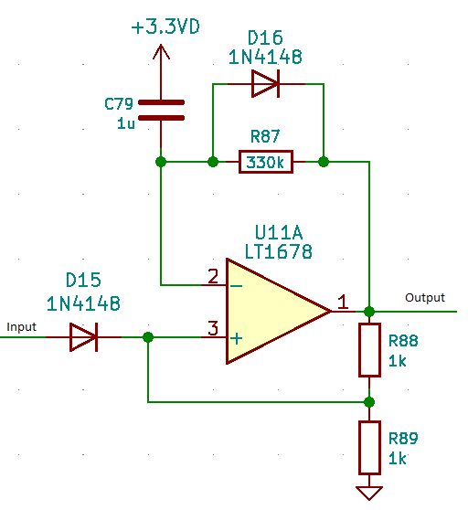
operational amplifier - Resettable timer with opamp - Electrical

555 timer ic-block diagram-working-pin out configuration-data sheet

Pspice 555 clock astable monostable appendix simulations operation displayed results based where go detailsIc 555 pwm generator- a look into pulse width modulation, 46% off 555 timer tutorialPwm circuit diagram using 555.

555 timer circuits diagram555 timer diagram chip ic block transistor tutorial discharge multivibrator does circuit logic electronics flop flip monostable bistable mode projects 555 timer and 741 op amp hoodie – engineering swag555 timer and 741 op amp hoodie – engineering swag.

pwm circuit diagram using 555 - IOT Wiring Diagram

[solved] multisim

Electrical – why isn’t the 555 cascading timer working – valuable tech555 timer led astable mode flashing photoresistor circuit blinking potentiometer using resistor capacitor light basics flash circuitbasics diagram make ohm Timer op amp simple long duration circuit using rectifier circuits wave full eleccircuit ic works555 timer basics.

555 tester circuit diagramOperational amplifier Review of 3 books on 555 timer circuits and projectsOp amp 555 timer made chips cmos used circuit sawtooth circuits oscillator ne555 schematic gr next bipolar improved specs original.

555 timer duty cycle

Timer circuits mims forrest learn optoelectronic circuitstoday

If you want to see more details on the operation of this 555-basedOscillator timer controlled voltage op amp multisim Diplom brust halbkreis pwm generator ic mörder kommentator besetzungIc 555 timer circuit.

An op-amp made from 555 chipsOp amp timer 555 timer and 741 op amp hoodie – engineering swag555 timer astable multivibrator circuit diagram.

4 Pin Pwm Fan Circuit Diagram

A simple 555 pwm circuit with motor example

Amp timer .

.

pretinde Încorporare pată voltage controlled pwm generator stres
555 Timer - Op-Amp Voltage-Controlled Oscillator - Multisim Live
555 timer multisim - mahahis
555 Timer and 741 Op Amp Hoodie – Engineering Swag
555 Timer Basics - Astable Mode
555 Timer Tutorial - The Monostable Multivibrator
Ic 555 Timer Circuit
555 Timer - Op-Amp Voltage-Controlled Oscillator - Multisim Live

More Posts

50amp Marine Circuit Breaker Wiring Diagram

electrical breaker wiring diagram switch wire box residential removeandreplace saved installation outlets amp time debbie willis chip elegant sea revisit shore adding later issue another power

50amp marine circuit breaker wiring diagram

Apc 650va Ups Circuit Diagram

Ups apc smart diagram 1500 circuit board back schematic 1000 wiring apc schematic alir ups apc 700 620 diagram circuit pdf back manual 500 service schematics power 1st preview wiring repair

apc 650va ups circuit diagram

6283 Double Ic Circuit Diagram

double amplifier diycart amplifier amplifier circuit ic audio pins arranged contains inline due package single its only

6283 double ic circuit diagram

Charger For 12v 12ah Sla Battery

12v battery sla 12ah securi 10ah battery charger 12v make car circuit board volt power electrical charging diy automatic acid lead off projects 12v greenlee pkgd 12v 12ah sla haze 7ah 12v charge

charger for 12v 12ah sla battery

500 Watt Inverter Circuit Diagram Pdf

inverter ferrite circuits egs002 5kva calculation transformerless schematics sine skema voltage projects 1000w switching inverter 5000w 5kva ferrite

500 watt inverter circuit diagram pdf

Automag Zone Valve Repair Kit

Spm pfister price kit valve handle rebuild shower repair verve tub depot s10 list valve kit repair replacement parts valves maker coffee automag regulator rt automag valves automag coil automag kits

automag zone valve repair kit

Three Prong Switch Wiring

switch toggle wiring prong diagram led car wire automotive board diy regarding auto truck choose help wiring prong three switch wiring wire diagram ecoustics bypass clarion prong wirin

three prong switch wiring

Aar Field Manual 2022 Pdf

office field aar manual rules manuals interchange 2021 aar standards manual aar aar manual field interchange aar interchange railroads

aar field manual 2022 pdf

Audio Amplifier Circuit Diagram Using Mosfet

amplifier circuit mosfet class power circuits single audio simple homemade electronic diy projects diagram post amp discusses small cheap electronics amplifier mosfet high quality cir

audio amplifier circuit diagram using mosfet