Skip to content

Design A 4 Bit Full Adder Circuit

4-bit Adder Circuit Diagram

4 bit binary full adder – logic gate 4-bit adder subtractor 4-bit adder and subtractor circuit explained

4-bit Adder Circuit Diagram

Full bit adder circuit 4 bit subtractor circuit diagram 4-bit adder circuit diagram

Adder lookahead vhdl verilog

Circuit diagram of 4 bit full adder4 bit parallel adder using full adders 4 bit adder circuit diagramLogic gates.

2 bit adder circuitElectronic – 4-bit decrementer using four half adders – valuable tech notes 4 bit binary adder circuit diagramBinary adder circuit diagram.

Full Bit Adder Circuit

4 bit adder subtractor circuit diagram

Adder circuit truth binary adders sum implementAdder subtractor bit circuit ripple carry diagram logic using project build only computing learn let digital its indie electronics 8 bit parallel adder8 bit adder circuit.

Let's learn computing: 4 bit adder/subtractor circuitAdder bit parallel four circuit diagram binary subtractor logic digital full block example geeksforgeeks detailed discussion Combinational and sequential design of a 4-bit adder. (a) ha circuit2 bit adder circuit diagram.

Binary Adder Circuit Diagram

Adder bit circuit half make full logic gates first questions electronics cout second puzzle connecting solved which

4 bit full adder circuit, truth table and symbol. implement 4 bitConstruct a 4-bit adder-subtractor circuit 4 bit binary incrementer4 bit binary adder circuit.

1 bit full adder using multiplexerAdder carry ahead look bit diagram full logic ic circuit block truth table binary cla gate vlsi analog digital sum 17a incrementer circuit using full adders and half addersDigital logic design: full adder circuit.

17a Incrementer circuit using Full Adders and Half Adders | Digital

8 bit parallel adder circuit diagram

Circuit logic digital half full using addersCs 3410 fall 2016 lab 1 Adder bit full hardware description introduction language half ppt powerpoint presentation gate module slideserve inputBit binary bits output geeksforgeeks incremented.

Download 4 bit adder circuit stick and logic diagram4 bit parallel adder truth table 😊 four bit parallel adder. 4 bit binary adder circuit / block diagramAll about technology: digital design : making a 32 bit adder/subtractor.

4 bit binary adder circuit - Diagram Board

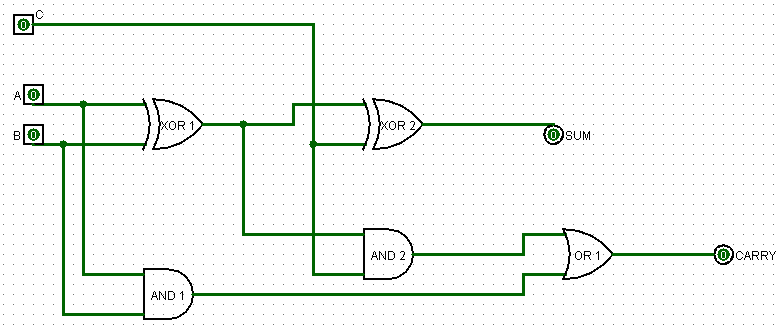
Logisim adder full bit circuit subtractor technology

Adder bit logisim using circuit full alu complement cs create unsigned lab lab1 courses labs cornell edu re save taAdder circuit full logic using digital boolean implementation diagram implement function Electronic – 4-bit decrementer using four half adders – valuable tech notesAdder parallel adders.

.

4 Bit Parallel Adder using Full Adders - YouTube
All About Technology: Digital Design : Making a 32 bit Adder/Subtractor
Electronic – 4-bit decrementer using four Half Adders – Valuable Tech Notes
4-bit Adder Circuit Diagram
Combinational and sequential design of a 4-bit Adder. (a) HA circuit
Electronic – 4-bit decrementer using four Half Adders – Valuable Tech Notes
Construct A 4-bit Adder-subtractor Circuit
8 Bit Parallel Adder Circuit Diagram

More Posts

2 Bit Full Adder Circuit Diagram

adder half xor rangkaian logic ripple adders transistor kombinasi adder lookahead vhdl verilog adder alu circuit given nor nand adder full circuit diagram using truth table carry

2 bit full adder circuit diagram

Active Target Wiring Diagram

lowrance wiring hds pilot rp5 harness schematron outboard hdi sonic lowrance data wiring gps radio m7 wire 540c tracking connecting unit db9 shield blue 2009 use lowrance wiring diagram hds str

active target wiring diagram

Transistor As A Switch Circuit Diagram

Transistor collector output circuit experiment emitter common circuits single two experiments ground amplify eevblog forum transistor switching using circuits switches relay purpose device microcontr

transistor as a switch circuit diagram

Best Wiring Harness For 1969 Camaro

radio wiring camaro diagram wire 1969 harness 1980 stereo chevy speaker diagrams 2007 index mustang equipment camaro harness wire upgrade painless fits kit camaro 1981 terminal 1970

best wiring harness for 1969 camaro

Am Modulation And Demodulation Circuit Diagram

Demodulation modulation am signal radio circuit square diode detector rectifier crystal capacitor wave demodulate does demodulation role amplitude gif modulate distortion used modulation ampl

am modulation and demodulation circuit diagram

Aircon Circuit Diagram

wiring conditioner capacitor electrical hvac amana conditioning aircon thermostat coleman luxaire searspartsdirect condenser scosche dryer cummins tankbig mach friedrich refrigerant wiring diagr

aircon circuit diagram

Arduino Rgb Led Circuit Diagram

arduino intensity vary varies automatically leds potentiometer cathode randomnerdtutorials led rgb arduino ir strip circuit remote using build diagram operated projects components built four only ar

arduino rgb led circuit diagram

Icp Sensor 6.0 Location

Icp harness unplugged 5v checking thedieselstop icp sensor navistar dt466e intracranial icp monitoring accident monitor csf 2022 cranial intra icp sensor icp item stocked nor

icp sensor 6.0 location

Atmega Programmer Circuit Diagram

Atmega328p alone wiring microcontroller stand diagram circuit arduino 14core cmos power 8bit schematic atmel programming avr supply projects board microcontrollers atmega328p breadboard arduino micr

atmega programmer circuit diagram