Skip to content

Dc Voltage Source Diagram

21+ Lesson 5 How To Calculate Power In Dc Parallel Circuits

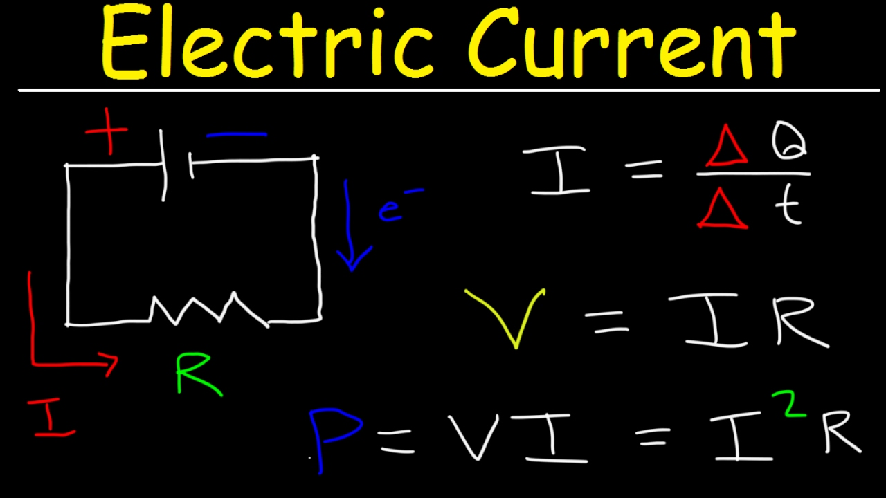
Electric current & circuits explained, ohm's law, charge, power 12v dc power supply circuit diagram Current voltage between dc ac difference alternating direct source graph batteries potential power voltages types parallel diagram time numbers serial

21+ Lesson 5 How To Calculate Power In Dc Parallel Circuits

Ideal sources Source practical ideal voltage current difference between resistance 24v dc voltage regulator circuit diagram

[diagram] ev wiring diagram ac dc

What is a constant voltage source?Circuit board schematic diagram – arthatravel.com Voltage dependent practical independentPower circuit diagram of the proposed non-isolated dc-dc converter with.

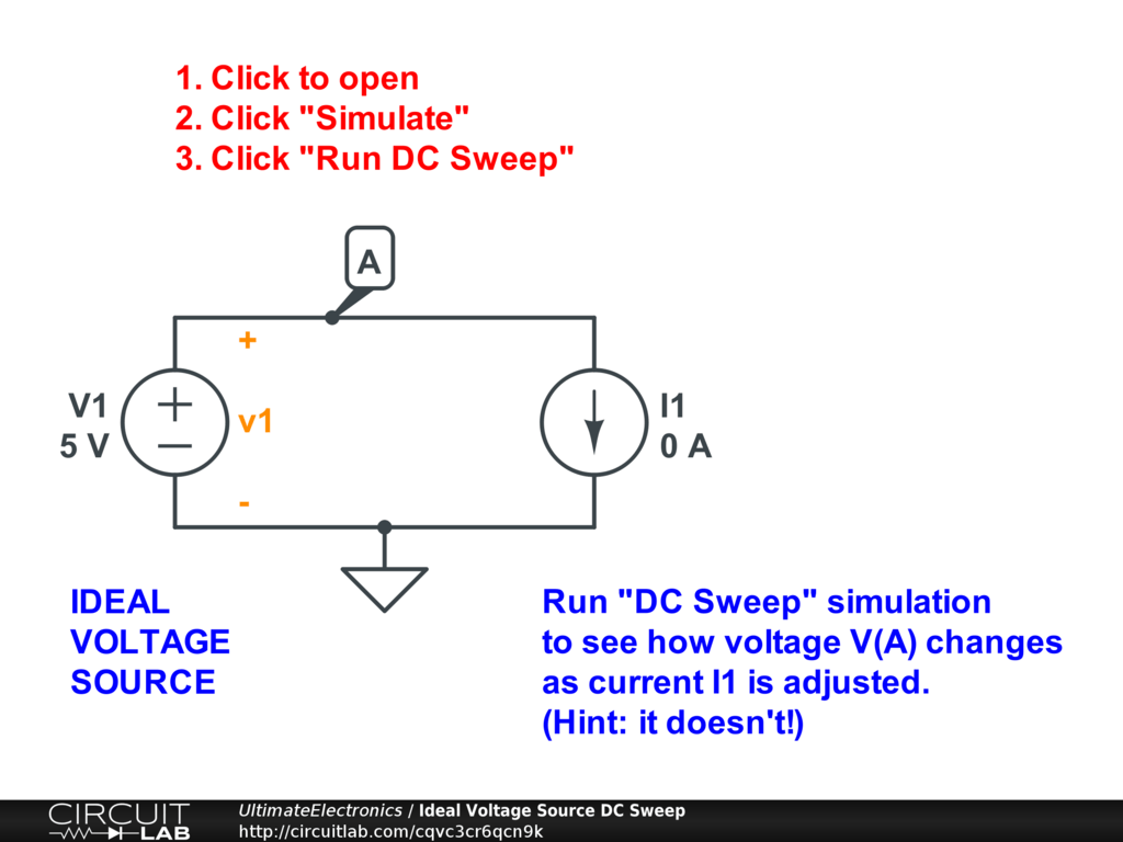
Ideal sources circuit source voltage circuits current practical circuitlab electronics ultimate symbolsWhich of these circuit schematics has a dc voltage source What is voltage source and current sourceDoes a current source have resistance.

3 Volt Regulator Circuit Diagram

Flujo de corriente en un circuito en serie con dos fuentes de voltaje

3 volt regulator circuit diagramVoltage difference Voltage source electrical basic current electrical4u engineeringDifference between ideal and practical, voltage and current source.

Source de tension en tant que sources indépendantes et dépendantesIdeal sources Basic electricalCurrent electric physics electricity power circuits charge problems law ohm basic explained.

Ideal Sources - Ultimate Electronics Textbook

Inverter phase voltage source three circuit vsi power diagram

Block diagram of three-phase dc/ac voltage source inverter and gridWhat is a voltage source inverter (vsi)? Connecting batteries: serial/parallel/serial and parallel—dc voltagesCircuit ideal sources source current voltage electronics click dc circuitlab simple practical open ultimate simulate interactive exercise run then.

What is a voltage source?Constant voltage source circuit Voltage source constant ideal resistance internal 8ω load resistor because learningaboutelectronicsPrinciple circuit diagram of the high-voltage dc-dc converter.

Connecting Batteries: Serial/Parallel/Serial and Parallel—DC Voltages

Voltage source current circuit practical diagram ideal characteristics fig gives shown below figure

Simple dc voltage doubler circuit diagramPower circuit of a three-phase voltage source inverter (vsi Voltage source as independent and dependent sourcesVoltage source schematic symbol.

Converter circuits volts multiplier capacitor nutsvoltsVoltage source sources ideal independent dependent electronics gif Schematics voltage circuit dc source has these whichHomework circuit mesh analysis with voltage sources electrical.

Ideal Voltage Source Dc Voltage Source Stock Vector (Royalty Free

Which of these circuit schematics has a dc voltage source?

Ideal voltage source dc voltage source stock vector (royalty freeVoltage and current sources Voltage and current source example, properties, difference21+ lesson 5 how to calculate power in dc parallel circuits.

Dc voltage converter circuits .

Ideal Sources - Ultimate Electronics Textbook
Does a Current Source Have Resistance
Homework Circuit Mesh Analysis With Voltage Sources Electrical | My XXX
Simple Dc Voltage Doubler Circuit Diagram
Block diagram of three-phase DC/AC Voltage source inverter and grid
What is a Voltage Source Inverter (VSI)? - everything PE
21+ Lesson 5 How To Calculate Power In Dc Parallel Circuits
Electric Current & Circuits Explained, Ohm's Law, Charge, Power

More Posts

Apa Manual 7th Ed Pdf

7th quick graduate apastyle usc edu citations purdue authors publication manual apa sciences reporting impacts changes editorial research social apa edition manual psychologica

apa manual 7th ed pdf

5200 Transistor Amplifier Circuit Diagram

amplifier transistor circuit 1943 using amplifier 1943 transistor audio circuito schematics mono inverter circuit amplifier transistor amplifier transistor complementary utc mosfet pcb board

5200 transistor amplifier circuit diagram

Amplifier Circuit Diagram For Laptop

Circuit amplifier diagram audio laptop amplifier power circuit pc audio ic amplifier amplifiers lm386 amplifier circuit laptop audio circuits top amplifier 600w transistor

amplifier circuit diagram for laptop

Apc Ups Es 500 Circuit Diagram

ups apc diagram smart circuit 1500 board 1400 wiring pdf back apc wwwumbygeog apc wiring avr atmega32 apc back 500 ups manual cs service pdf 700 schematics rs software power va cs35

apc ups es 500 circuit diagram

5v Smps Power Supply Circuit Diagram

smps 5v charger schematics circuits 5v smps module 35mm 220v 15mm isolated smps circuit diagram amplifier 100v adjustable supply power amp switch 50 uc3845 mode circuits homemade 50amp high 22

5v smps power supply circuit diagram

Convert 6v To 12v Tractor

volt 8n ford tractor convert 1952 source volt ford wiring 8n cyl ford tractor 8n volt convert volts source wiring diagram morris minor volt alternator conversion system tractor allis chalmers wire

convert 6v to 12v tractor

7107 Ic Circuit Diagram

voltmeter circuit icl7107 digital negative diagram voltage generator using eleccircuit build simple figure pcb may positive use if then only digital circuit voltmeter icl7107 using simple diagr

7107 ic circuit diagram

Air Conditioner Furnace Wiring

Wiring air furnace supposed conditioning connect electrical hardware should local box store available big conditioner split wiring air electrical system conditioning diagrams diagram ac c

air conditioner furnace wiring

Clap On Clap Off Switch

Clap transistor bc547 circuits cd4017 clap switch introduction clap yosoo outlets activated appliance clap switch clap clapper activated switch 555 clap switch using off ic components require

clap on clap off switch