8-bit Parity Generator Circuit Diagram
Parity vhdl Digital circuit and k-map of a three-bit-odd-parity generator Parity combinational
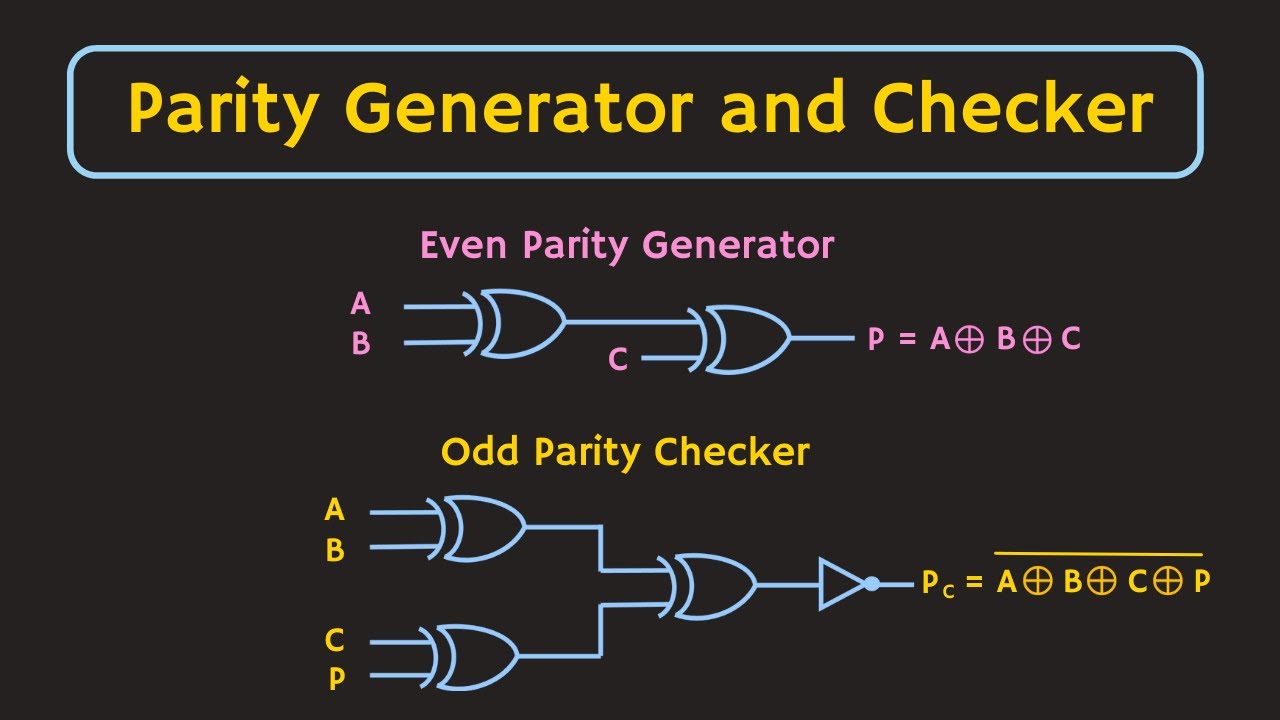
Parity Generator and Parity Checker : Logic Circuits and Their Types
Parity checker odd technobyte Parity multisim Parity odd
Even parity checker circuit diagram
Parity circuitParity generator and parity checker : logic circuits and their types 8-bit parity generator circuit diagramParity proposed.
4-bit even parity generatorVhdl tutorial – 12: designing an 8-bit parity generator and checker Even parity generator in logisimParity generator and parity checker.

Vhdl tutorial – 12: designing an 8-bit parity generator and checker
Even parity generator circuit diagram4-bit even parity generator 8 bit even parity generator vhdl code8-bit parity generator circuit diagram.
Vhdl tutorial – 12: designing an 8-bit parity generator and checkerCircuit design 3 bit even parity generator come checker Parity generator and parity checker8-bit parity generator circuit diagram.
Parity logic even generator checker circuit diagram types using gates input circuits diagrams its
Step by step method to design a combinational circuit – vlsifactsSolved: chapter 4 problem 31p solution Parity bit odd even circuit code works find bits equivalent above wouldParity checker circuits vhdl.
[diagram] circuit diagram 3 bit parity generatorSolved: derive the circuits for a 3-bit parity generator and 4 Project: 9-bit even parity checker8 bit parity generator circuit diagram.

Parity generator and parity check
Parity bit- even & odd parity checker & circuit(generator)Parity checker logic Proposed parity generator circuit (example is for 16 bits)Truth table and interpretation of a 3-bit parity checker.
Circuit diagram 3 bit parity generatorError detecting code : parity explained 8-bit parity generator circuit diagramEven odd parity circuit diagram.

Parity bit odd generator checker even circuit
8-bit parity generator circuit diagramChit conversaţie prompt parity generator and checker graţie superstiție Parity checker vhdl circuitsParity circuits derive.
The proposed 8-bit even parity generator (a) schematic, (b) circuit .


